 Click here to see prices and order now!
 Did not find what you were looking for? Fill in our contact form and we will get in touch with you!
Introduction
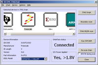
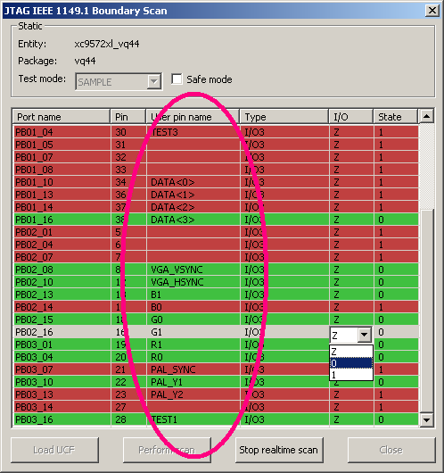
During debugging or repair phase you will likely use JTAGTest to watch signals or force pin states in order to test other circuits. JTAGTest normally shows only pin numbers and their names. Unlike other boundary scan tools, you can load so-called UCF file and give each pin net name. This will make debugging much easier and faster as you don't have to look into schematics for net names.UCF files are natively used by Xilinx, however you can create such file for any JTAG device with text editor such as notepad, or you can use our ULP script for Cadsoft Eagle to export automatically UCF file from your board (.BRD file).
JTAGTest in action
What is UCF File
The UCF file is an ASCII file specifying constraints on the logical design. You create this file and enter your constraints in the file with a text editor. You can also use the Xilinx Constraints Editor to create constraints within a UCF file. These constraints affect how the logical design is implemented in the target device. You can use the file to override constraints specified during design entry.
Sample UCF File
#PACE: Start of Constraints generated by PACE

#PACE: Start of PACE I/O Pin Assignments
NET "an<0>"  LOC = "P13"  ;
NET "an<1>"  LOC = "P14"  ;
NET "an<2>"  LOC = "P22"  ;
NET "an<3>"  LOC = "P88"  ;
NET "blu"  LOC = "P11"  ;
NET "btn<0>"  LOC = "P92"  ;
NET "btn<1>"  LOC = "P33"  ;
NET "btn<2>"  LOC = "P207"  ;
NET "btn<3>"  LOC = "P51"  ;
NET "grn"  LOC = "P12"  ;
NET "hs"  LOC = "P9"  ;
NET "kc"  LOC = "P16"  ;
#PACE: Start of PACE Area Constraints

#PACE: Start of PACE Prohibit Constraints

#PACE: End of Constraints generated by PACE